

 English
 русский
 Español
Home / News / Industry News / Which Design Details Should Buyers Confirm Before Ordering Custom Extension Springs
Which Design Details Should Buyers Confirm Before Ordering Custom Extension Springs
Industry News-A spring drawing may look straightforward, but a small difference in wire diameter, hook geometry, or initial tension can change how a component performs after installation. For equipment manufacturers, automotive parts suppliers, and industrial buyers, defining these details before requesting a quotation helps reduce design adjustments and sample revisions.
At Heli Spring, we manufacture custom extension springs according to customer drawings, physical samples, and application requirements. Our OEM and ODM services cover spring dimensions, material selection, end configurations, and functional specifications. We work with customers to review these requirements before production so that the finished springs can match their intended mechanical applications.
Several technical details deserve attention during the purchasing process. The following guide explains the information buyers should prepare and the questions worth discussing with our engineering team.

1. Define the Application and Working Conditions
Before discussing spring dimensions, we recommend describing how the spring will operate inside the equipment. An extension spring generates pulling force as it stretches, making it suitable for mechanisms that require return movement, tension control, or mechanical positioning.
The application determines the mechanical requirements and helps us evaluate an appropriate spring structure.
Important application information
- Installation position: Explain whether the spring is mounted horizontally, vertically, or at an angle.
- Operating frequency: State how many extension and return cycles the spring is expected to complete during normal operation.
- Working load: Provide the pulling force required during normal operation and under any specified peak-load conditions.
- Available space: Identify the permitted spring diameter and overall installed length.
- Environmental conditions: Describe exposure to moisture, dust, chemicals, outdoor weather, or temperature variations.
For example, a spring used in an automotive seat adjustment mechanism may experience repeated loading and vibration. A spring installed in an electrical enclosure may have different requirements regarding corrosion resistance and available mounting space. These differences affect our engineering recommendations.
2. Confirm Wire Diameter and Spring Body Dimensions
Dimensional specifications form the foundation of a spring drawing. Wire diameter, coil diameter, body length, and total length determine whether the spring can fit into the assembly and operate within its intended movement range.
Key dimensions to include in the drawing
| Parameter | Description | Purchasing Consideration |
| Wire Diameter (d) | Thickness of the spring wire | Specify the required diameter and tolerance. |
| Outside Diameter (OD) | External diameter of the spring body | Check clearance inside the assembly. |
| Inside Diameter (ID) | Internal diameter of the coiled body | Confirm available space around internal components. |
| Mean Coil Diameter (D) | Average diameter measured through the wire centerline | Provides an important reference for spring calculations. |
| Body Length | Length of the coiled section | Distinguish body length from overall spring length. |
| Free Length | Overall length without an external pulling load | Define the measurement reference, including hook dimensions. |
| Active Coil Count | Number of coils contributing to spring deformation | Helps determine the spring rate. |
We recommend providing both a general assembly drawing and a detailed spring drawing. An enlarged view of the spring ends can also help clarify dimensions that may not be visible in the main drawing.
For customized projects without complete engineering drawings, our technical team can review physical samples, sketches, or available dimensional information to discuss a suitable design.
3. Choose the Appropriate Hook Configuration
Hooks connect an extension spring to the surrounding mechanical structure. Their geometry affects mounting compatibility, load transfer, installation clearance, and mechanical durability. A suitable spring body cannot compensate for an end configuration that does not fit the application.
Common hook and loop designs
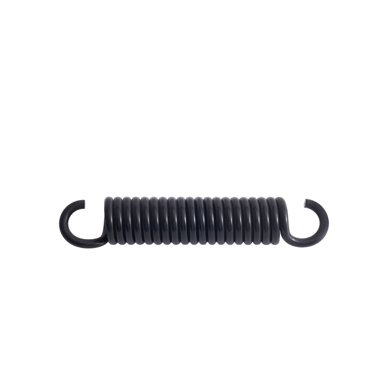
- Machine Hooks: These ends are formed into a loop configuration suitable for various mechanical connections.
- Cross-Center Loops: The loop extends across the spring centerline and can be used in applications requiring a particular mounting arrangement.
- Side Hooks: These configurations provide an alternative connection direction for assemblies with limited mounting space.
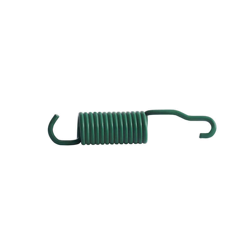
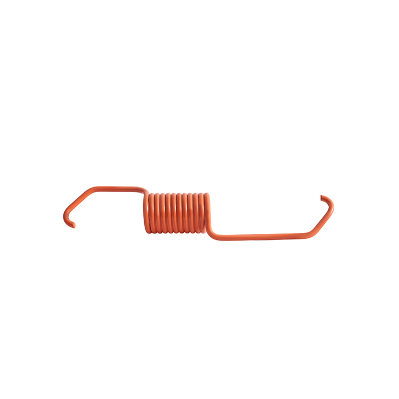
- Extended Hooks: Longer end sections can provide additional clearance between the spring body and the mounting point.
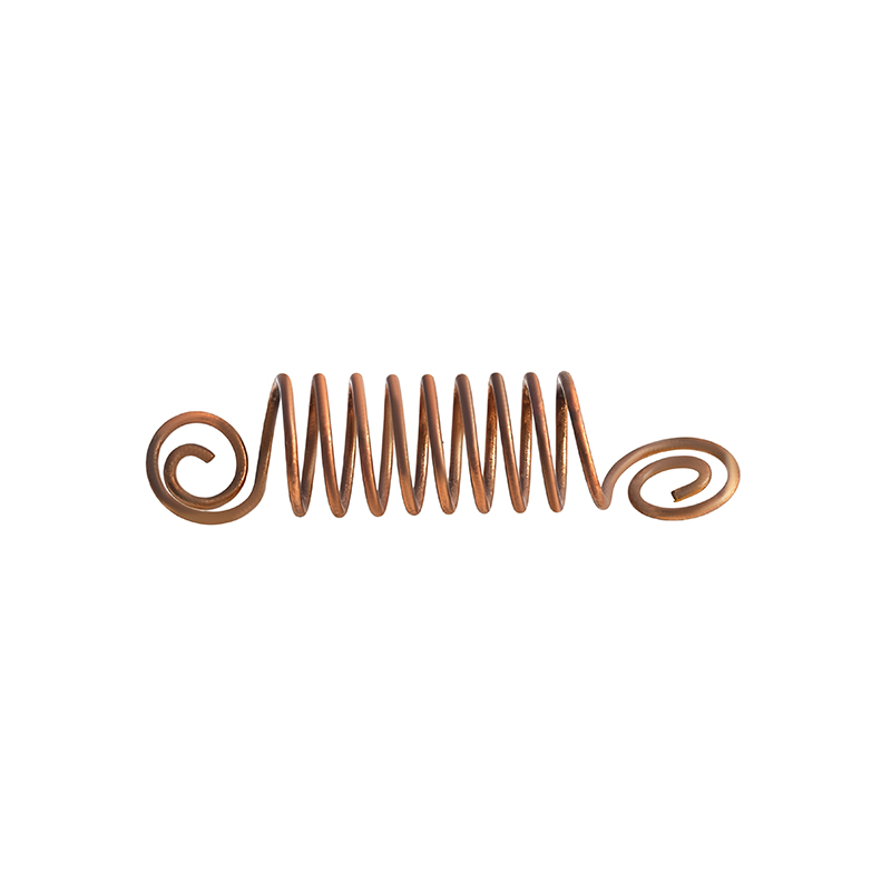
- Customized End Forms: Special loops, bends, and connection structures can be developed according to application drawings.
Details buyers should specify
Rather than describing a hook simply as standard or customized, we recommend providing measurable information:
- Hook opening width and inside diameter.
- Hook length and bending radius.
- Distance between the hook and spring body.
- Relative orientation of both spring ends.
- Mounting pin diameter and bracket thickness.
Hook areas deserve particular engineering attention because bending during manufacturing creates localized stress. For applications involving repeated loading, we assess the end geometry alongside the spring body rather than treating the hooks as simple connection accessories.
4. Establish Initial Tension and Working Force Requirements
Initial tension is an important characteristic of close-wound extension springs. It refers to the internal force holding adjacent coils together. An external pulling force must overcome this resistance before the spring begins to extend.
After the initial tension has been overcome, the pulling force generally increases with additional extension. Buyers should therefore provide measurable force requirements instead of using descriptions such as strong tension or light tension.
Basic extension spring force calculation
For preliminary engineering evaluation, the relationship between force, initial tension, and spring extension can be expressed as:
F = Fi + k × x
- F: Total pulling force at the specified extension.
- Fi: Initial tension of the spring.
- k: Spring rate, usually expressed in N/mm.
- x: Extension beyond the reference point at which the coils begin to separate.
Consider an illustrative design with an initial tension of 3 N and a spring rate of 0.4 N/mm. At an additional extension of 15 mm, the calculated pulling force is:
F = 3 + (0.4 × 15) = 9 N
This example demonstrates how initial tension and spring rate work together. Actual spring calculations must also consider material properties, coil geometry, allowable stress, and the intended operating range.
Force information to include in an RFQ
| Requirement | Example Information |
| Initial Tension | 3 N, subject to agreed tolerance |
| Spring Rate | 0.4 N/mm |
| Working Extension | 15 mm beyond the initial tension point |
| Calculated Working Force | 9 N |
| Maximum Working Extension | Defined according to the application drawing |
At Heli Spring, we recommend specifying force values at one or more defined extension lengths. This gives our engineering and quality teams measurable references for sample evaluation and subsequent production inspection.
5. Select Spring Materials According to Service Conditions
Material selection affects tensile strength, fatigue behavior, corrosion resistance, and manufacturing suitability. The appropriate material depends on the required mechanical performance and the environment surrounding the spring.
Common material options
| Material | Typical Characteristics | Potential Applications |
| Spring Steel | Suitable mechanical strength and elasticity | General industrial mechanisms and hardware. |
| Piano Wire (SWP) | High tensile strength and consistent wire properties | Precision mechanical components. |
| Stainless Steel (SUS) | Corrosion resistance, depending on grade | Electrical equipment, outdoor hardware, and moisture-exposed assemblies. |
| Phosphor Bronze | Electrical conductivity and corrosion resistance | Electrical contacts and specialized mechanisms. |
| Chrome Silicon | Suitable strength and fatigue characteristics for demanding spring applications | Applications requiring specific mechanical performance. |
Heli Spring manufactures springs using various materials, including SWC spring steel, SWP piano wire, stainless steel, phosphor bronze, and other specified alloys.
During material discussions, we recommend confirming the following details:
- Required material grade and applicable material standards.
- Operating temperature range.
- Exposure to humidity, salt, chemicals, and cleaning agents.
- Required mechanical properties and fatigue expectations.
- Material certificates or other documentation requirements.
Stainless steel is not a universal solution for every environment. The exact grade should be evaluated according to both corrosion exposure and mechanical loading conditions.
6. Specify Surface Treatment and Appearance Requirements
Surface treatment can influence corrosion protection, appearance, and compatibility with surrounding components. Buyers should identify the required finish during the quotation stage rather than adding this requirement after sample production.
Our available surface treatment options include:
- Nickel plating.
- Zinc galvanizing.
- Black oxidation.
- Electrophoresis.
- Powder coating.
- Passivation and polishing.
- Phosphate treatment.
Not every treatment is appropriate for every spring material or application. Buyers should also consider coating thickness, dimensional changes, surface appearance, and any relevant environmental restrictions.
For assemblies with close dimensional clearances, we recommend reviewing the finished dimensions after surface treatment. This helps avoid interference during installation.
7. Set Practical Tolerances and Inspection Standards
Dimensional tolerances and force tolerances should reflect the actual function of the spring. Applying unnecessarily tight tolerances to every dimension can increase manufacturing complexity without providing a corresponding benefit to the assembly.
Critical inspection items
- Dimensional inspection: Check wire diameter, outside diameter, body length, and overall free length.
- Hook inspection: Verify opening dimensions, bending geometry, and end orientation.
- Force testing: Measure initial tension and pulling force at the agreed extension lengths.
- Surface inspection: Check for visible cracks, scratches, corrosion, and coating defects.
- Functional evaluation: Confirm that the spring operates correctly with representative mounting components.
At Heli Spring, our testing equipment includes tensile testing machines, fatigue testing machines, and hardness testers. These resources support dimensional and mechanical evaluations during customized spring development.
Buyers should also define inspection frequency, sampling requirements, and reporting formats according to their quality management procedures. A clear inspection agreement helps both parties work with the same acceptance criteria.
8. Review Samples Before Authorizing Production
A prototype provides an opportunity to evaluate the spring in its actual operating environment. We recommend checking more than the physical appearance of the sample before approving a production drawing.
Sample approval checklist
- Compare all critical dimensions against the approved drawing.
- Install the spring using the intended mounting pins or brackets.
- Verify the initial tension and working force.
- Check the permitted extension.
- Evaluate hook deformation under the specified working load.
- Conduct cycle testing under representative operating conditions, where required.
- Record any dimensional or functional adjustments before approving the final specification.
For applications involving repeated movement, sample testing should reflect the actual load, extension range, operating speed, and environmental conditions as closely as practical. A simple installation check cannot replace fatigue evaluation for demanding applications.
Once the sample is approved, the drawing, material specification, inspection requirements, and approved reference sample should be maintained as production documents. This provides a consistent basis for subsequent orders.
9. Prepare a Complete RFQ for Custom Spring Manufacturing
A well-prepared request for quotation helps our team evaluate the design and communicate technical requirements more efficiently. Missing information does not necessarily prevent an initial discussion, but providing more engineering details makes the quotation and sample-development process clearer.
We recommend organizing the following information before contacting Heli Spring:
| RFQ Category | Information to Prepare |
| Product Identification | Spring name, part number, and application. |
| Technical Drawing | 2D drawing, 3D CAD file, sketch, or physical sample. |
| Dimensions | Wire diameter, coil diameter, body length, and free length. |
| End Configuration | Hook type, opening, length, and orientation. |
| Mechanical Requirements | Initial tension, spring rate, working load, and extension range. |
| Material | Material grade and required documentation. |
| Surface Finish | Plating, coating, passivation, or other specified treatment. |
| Quality Requirements | Critical tolerances, inspection methods, and testing standards. |
| Order Information | Expected order volume, packaging requirements, and delivery destination. |
At Heli Spring, our OEM service supports manufacturing based on customer drawings and samples. Our ODM service also allows customers to discuss spring structures and technical parameters with our engineering team based on their application requirements.
Related products
If you are interested in our products, please consult us
CONTACT DETAIL
- Email: helispring@163.com
- Tel: +86-18767775615
- Address: Jinlu Industrial Zone, Beibaixiang Town, Yueqing, Wenzhou City, Zhejiang Province, China.
PRODUCTS
MOBILE TEMERNAL
Wenzhou Heli Spring Manufacturing Co., Ltd. ALL RIGHTS RESERVED.

China Customized Spring Manufacturer