
 English
 русский
 Español
Comprehensive Guide to Torsion Springs Types Design and Applications.
Industry News-Comprehensive Guide to Torsion Springs: Design, Types, and Applications
Part 1: What is a Torsion Spring?
A torsion spring is a spring that stores and releases mechanical energy by resisting rotation (twisting) about its axis. When an external force is applied to the ends of the spring (called "legs" or "arms"), causing it to rotate about its central axis, the spring generates a torque (torque) proportional to the angle of rotation, attempting to return the spring to its original position.
Core Functions:
- Storing Angular Energy: Energy is stored during torsion and released during unloading.
- Providing Rotational Force: Generates torque to drive a mechanism or maintain position.
- Providing Restoring Force: Returns a component to its original position after rotation.
Part 2: Main Types of Torsion Springs
Depending on their geometry and load application, torsion springs are classified into the following categories:
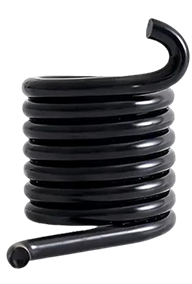
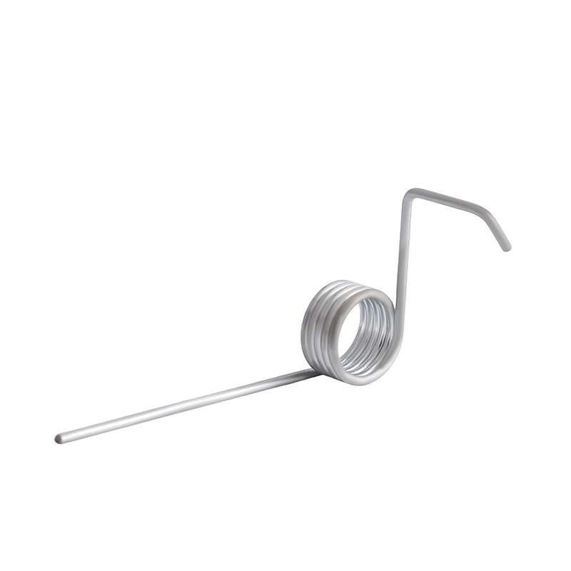
Single-Type Torsion Spring
- Description: This is the common type, consisting of a coiled wire with two arms extending to apply torque.
- Features: Simple structure and versatile applications. The arm shape (straight, hinged, short, or shaped) can be varied to suit specific installation and functional requirements.
- Applications: Clothes pins, mousetraps, automotive clutches, door hinges, and lever return mechanisms.
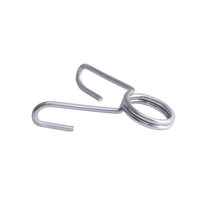
Double Torsion Spring
- Description: Consists of a right-handed and left-handed coil in series, usually with a separation point or sleeve in between.
- Features: At the same angle, its torque output is approximately twice that of a single torsion spring of the same specification, but with a shorter axial length. During operation, one coil tightens while the other relaxes.
- Applications: Applications where high torque is required but space is limited, such as joysticks in large game consoles, return mechanisms for tractor seats, and certain types of actuators.
Torsion Bar Spring
- Description: Rather than a coil, it consists of a straight or slightly shaped elastic rod. Torque is applied directly to both ends of the rod.
- Features: Typically made of high-strength alloy steel, it can store significant energy. It is lightweight and compact.
- Applications: Automotive suspension systems (especially trucks and performance vehicles), torsion bars in heavy machinery.
- Motor carbon brush springs (special types)
Torsion coil springs are mechanical devices designed to resist rotational forces, storing and releasing energy through angular deflection. Unlike compression or extension springs that operate linearly, torsion springs exert torque along their axis when the ends are rotated about the centerline. These components appear in numerous applications from simple clothespins to complex automotive systems.
Different Types of Torsion Coil Springs
Torsion coil springs are manufactured in several configurations, each suited to specific application requirements. The primary distinction involves the number of coils and their arrangement relative to the applied load.
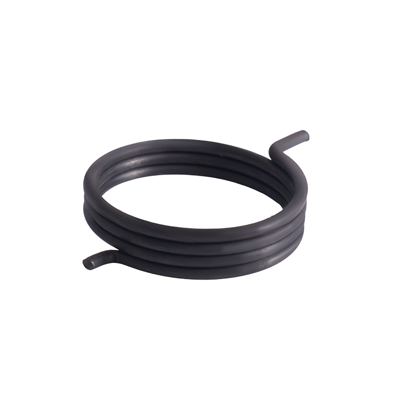
Single-bodied torsion springs consist of one continuous coil with two ends extending radially, axially, or tangentially. These represent the common configuration, used in applications ranging from door hinges to counterbalance mechanisms. The ends can be straight offset, hinged, or custom-designed for specific attachment points.
Double-bodied torsion springs feature two separate coil sections connected by a common end. This design provides balanced torque distribution and is frequently employed in applications where space constraints prevent using a single wider coil. Double-bodied springs offer symmetrical loading, reducing side thrust on supporting components.
Left-hand and right-hand wound springs describe the helix direction. Left-hand wound coils spiral in the direction of a left-hand thread, while right-hand wound follows a standard thread direction. The winding direction must match the intended rotation during loading to prevent the spring from binding or unwinding incorrectly.
Variable pitch torsion springs have coils spaced unevenly along the body. This design allows the spring to contact adjacent coils at specific deflection angles, altering the spring rate during operation. Variable pitch provides progressive torque characteristics where the resistance increases at a non-linear rate as deflection continues.
Non-circular section torsion springs utilise wire with square or rectangular cross-sections rather than round wire. The shaped wire allows higher energy storage within a limited space, as the moment of inertia can be optimised for the available envelope. Rectangular wire torsion springs are common in automotive and aerospace applications where space is constrained.
Multiple start torsion springs incorporate more than one coil start, similar to multi-start threads. These springs provide higher torque capacity within shorter body lengths by effectively having multiple springs operating in parallel within the same coil diameter.
Radial and axial end configurations refer to how the spring legs extend from the body. Radial ends extend outward perpendicular to the axis, axial ends extend parallel to the axis, and tangential ends extend at angles combining both directions. The end configuration must match the application's attachment method to ensure proper load transfer.
What defines a high-torque torsion spring?
High-torque springs are characterised by their ability to resist significant rotational forces relative to their physical size. These springs typically use larger diameter wire, rectangular cross-sections, or multiple coil bodies to achieve the required torque within space constraints. The specific torque value considered "high" depends on the application context and available installation space.
How does wire diameter affect torque capacity?
Torque capacity increases with the fourth power of wire diameter for round wire springs, making diameter one of the influential design parameters. A modest increase in wire diameter produces substantial torque capacity gains, though this also affects the spring's physical envelope and may require larger coil diameters to maintain proper stress levels.
What materials are suitable for high-torque applications?
High-torque torsion springs typically utilise oil-tempered wire, chrome silicon, or chrome vanadium alloys. These materials offer enhanced tensile strength and fatigue resistance compared to standard music wire. Stainless steel grades such as 302 and 316 provide corrosion resistance but generally have lower allowable working stresses than alloy steels.
Can high-torque springs operate at elevated temperatures?
Standard spring materials begin relaxing at temperatures above 150°F. For elevated temperature applications, specialised alloys such as Inconel or 17-7 PH stainless steel maintain their properties up to 500°F or higher, though material costs increase substantially. The operating temperature must be considered during design, as higher temperatures reduce available torque and may cause permanent set.
What is the maximum safe deflection for torsion springs?
Torsion springs are typically designed for deflection angles between 30 and 360 degrees, though specialised designs may exceed this range. The safe deflection limit depends on material properties, wire diameter, coil diameter, and the number of active coils. Exceeding recommended deflection angles increases stress beyond safe levels, potentially causing permanent deformation or fracture.
Torque-Angle Characteristics of Commercial Torsion Springs
Commercial torsion springs exhibit specific relationships between applied torque and angular deflection that determine their suitability for various applications. These characteristics follow predictable patterns governed by spring geometry and material properties.
The fundamental relationship between torque and angular deflection is approximately linear for torsion spring designs within their working range. This linearity means that doubling the deflection angle approximately doubles the resisting torque, assuming the spring operates within its elastic limit. The slope of this torque-angle curve defines the spring rate, expressed in force-distance per degree or radian of deflection.
Several factors influence the torque-angle characteristics observed in commercial springs. The number of active coils directly affects the spring rate, with more coils producing a lower rate for a given wire diameter and coil size. Each additional active coil increases the total deflection achievable before reaching material stress limits, while proportionally reducing the torque generated per degree of deflection.
The coil diameter significantly impacts the torque-angle relationship. Springs with larger mean diameters produce lower spring rates than smaller diameter springs of identical wire size and coil count, as the longer lever arm reduces the force required for deflection. This relationship follows an inverse cubic function, making coil diameter a powerful parameter for adjusting spring characteristics.
Common Modes of Failure for Torsion Coil Springs
Torsion springs experience several distinct failure mechanisms related to material fatigue, design limitations, or installation conditions. Understanding these failure modes helps identify root causes and implement corrective measures.
Fatigue fracture represents the common failure mode in cyclically loaded torsion springs. Cracks initiate at surface irregularities or stress concentrations and propagate through the wire cross-section until a sudden fracture occurs. Fatigue failures typically appear as smooth, beach-marked surfaces near the origin with rougher texture in the final fracture zone.
Stress relaxation manifests as a gradual loss of torque over time under sustained deflection. This phenomenon occurs when material creep causes permanent set, reducing the spring's ability to maintain specified torque. Elevated temperatures accelerate relaxation, though it occurs at ambient conditions in highly stressed springs.
Permanent set results from loading the spring beyond its elastic limit, causing plastic deformation that alters the free position and reduces available torque. This failure mode typically occurs during initial assembly or when operating conditions exceed design parameters, rather than developing gradually over time.
Surface cracks develop from manufacturing defects, including seams, laps, or die marks in the raw wire. These discontinuities act as stress concentrators, initiating premature cracking even under normal operating loads. Proper material inspection during manufacturing reduces but does not eliminate this risk.
End hook or leg failure represents a common fracture location where the spring attaches to mating components. The bending stresses at end transitions often exceed body stresses, particularly in designs with sharp radii or insufficient material at the bend. This failure mode frequently indicates inadequate end design for the applied load.
Coil binding damage results when adjacent coils contact during deflection, creating wear marks and stress concentrations at the contact points. Repeated binding may produce fretting corrosion or localised work hardening that initiates cracking, particularly in springs designed for high deflection angles.
Related products


If you are interested in our products, please consult us
CONTACT DETAIL
- Email: helispring@163.com
- Tel: +86-18767775615
- Address: Jinlu Industrial Zone, Beibaixiang Town, Yueqing, Wenzhou City, Zhejiang Province, China.
PRODUCTS
MOBILE TEMERNAL
Wenzhou Heli Spring Manufacturing Co., Ltd. ALL RIGHTS RESERVED.

China Customized Spring Manufacturer