

 English
 русский
 Español
Carbon Steel Compression Springs: Could Coil Binding Limit Travel
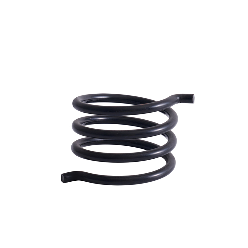
Industry News-Compact mechanical assemblies often require a compression spring to deliver reliable force within a surprisingly small space. A Carbon Steel Spiral Compression Spring can provide a useful combination of stiffness, resilience, and dimensional flexibility, but its working stroke is never unlimited.
One issue deserves particular attention: coil binding. This condition occurs when adjacent coils come into contact before the required compression stroke has been completed. Once the coils stack together, the spring has little or no remaining elastic travel. The result can be a sudden change in load behavior, unwanted stress, or reduced movement of the mechanism.
What Actually Limits Compression Travel?
The key dimension is known as solid height. It represents the spring length at which the coils have essentially closed together. The difference between free length and solid height provides the theoretical compression range, although the complete range should not normally be used as the working stroke.
- Free length: The unloaded length of the spring.
- Solid height: The approximate minimal length after the coils stack.
- Working deflection: The actual compression used during operation.
- Coil clearance: The remaining gap between adjacent coils during normal operation.
For a closed-and-ground compression spring, a simplified solid-height relationship is approximately the total coil count multiplied by wire diameter. End configuration and manufacturing tolerances can change the actual value, so production drawings should define the required dimensions carefully.
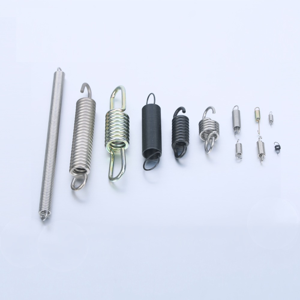
Example of Travel Calculation
| Parameter | Example Value | Design Significance |
| Wire diameter | 3.0 mm | Affects stiffness and solid height |
| Total coils | 8 | Contributes to stacked height |
| Free length | 60 mm | Available unloaded length |
| Approx. solid height | 24 mm* | Physical compression boundary |
| Travel to solid | 36 mm* | Not necessarily the working stroke |
*Illustrative calculation for a closed-and-ground configuration. Actual dimensions depend on the spring design and manufacturing specification.
Which Design Details Increase Coil Binding Risk?
1. Small Coil Pitch
Pitch describes the center-to-center spacing between adjacent coils. A tighter pitch leaves less clearance for compression. Under load, the available gap disappears sooner, increasing the possibility of coil-to-coil contact before the mechanism reaches its intended position.
2. Larger Wire Diameter
Increasing wire diameter generally raises spring stiffness, but it also increases the amount of material stacked at solid height. A thicker wire can therefore provide higher force within a given deflection while reducing the geometric space available at full compression.
For a Carbon Steel Spiral Compression Spring, wire diameter should therefore be considered together with free length, coil count, mean diameter, and required travel rather than treated as an isolated specification.
3. Excessive Working Deflection
A spring may have enough theoretical travel on paper yet still be unsuitable for repeated operation close to solid height. Reaching coil bind creates a sharp increase in mechanical contact and stress. Repeated solid-height compression can contribute to permanent set or premature failure.
How Can Product Specifications Reduce the Risk?
A practical specification should define the complete operating envelope rather than simply listing load and free length.
- Specify free length and working length.
- State wire diameter and outside diameter.
- Define total and active coil counts.
- Check solid height against the required compression stroke.
- Allow dimensional tolerance and operating clearance.
Spring rate is also closely connected with geometry. A commonly used relationship is k = Gd⁴ / (8D³Na), where d is wire diameter, D is mean coil diameter, and Na is the active coil count. This means a relatively small change in wire diameter can have a substantial effect on spring stiffness.
Could Coil Binding Be Avoided Without Sacrificing Load?
Usually, the answer depends on the complete spring geometry. Increasing free length can provide additional geometric travel, while changing wire diameter, mean coil diameter, or active coil count can alter the force-deflection relationship. A guide rod or housing can also help control lateral movement in certain assemblies, although excessive contact with the guide may introduce friction.
The key point is that a Carbon Steel Spiral Compression Spring should not be evaluated only by its load rating. Its usable travel depends on the relationship between free length, solid height, pitch, coil geometry, and working deflection. Keeping these factors aligned gives engineers more predictable compression behavior and helps prevent coil binding from becoming a hidden limitation in compact mechanisms.
Related products
If you are interested in our products, please consult us
CONTACT DETAIL
- Email: helispring@163.com
- Tel: +86-18767775615
- Address: Jinlu Industrial Zone, Beibaixiang Town, Yueqing, Wenzhou City, Zhejiang Province, China.
PRODUCTS
MOBILE TEMERNAL
Wenzhou Heli Spring Manufacturing Co., Ltd. ALL RIGHTS RESERVED.

China Customized Spring Manufacturer