

 English
 русский
 Español
Does Wire Forming Accuracy Change Clip Spring Performance
Industry News-A spring clip may look like a simple bent piece of wire, but its performance depends heavily on geometry. A Tolerant Wire Forming Clip Spring needs to maintain its designed shape closely enough to provide predictable clamping force, fit correctly inside the assembly, and return toward its intended position after repeated loading.
Small deviations at a bend can change the position of a contact point. A slightly different angle can also alter the amount of preload applied to the mating component. This makes wire forming accuracy a functional issue rather than simply a cosmetic or dimensional concern. Recent research and industry testing have linked spring-clip geometry with clamping force, stiffness, elasticity behavior, and assembly strength.
Why Does Clip Geometry Matter?
Unlike a simple cylindrical compression spring, a wire-form clip may contain several bends, straight sections, hooks, offsets, and contact points. Each feature contributes to the final mechanical response.
- Bend angle determines the orientation of the contact section.
- Overall height affects installation clearance and preload.
- Wire diameter influences stiffness and load capacity.
- Bend radius affects local stress distribution.
- End position controls how the clip engages with the mating component.
Consequently, a clip can remain within an acceptable overall length while still behaving differently because a critical bend has shifted from its nominal position.
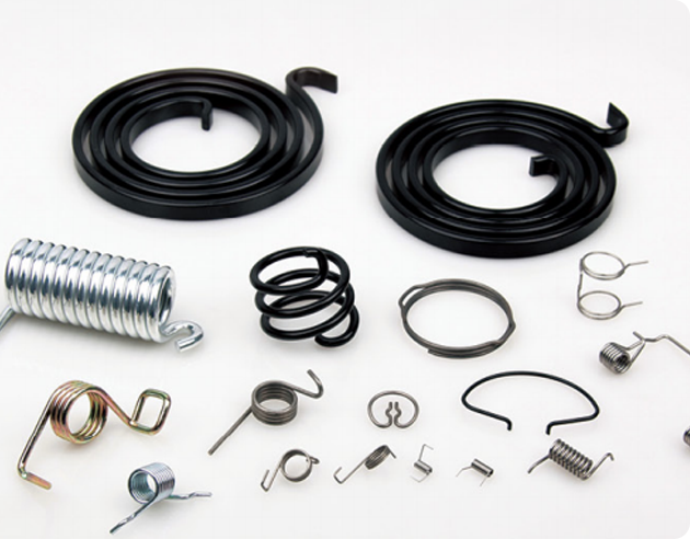
Which Forming Tolerances Deserve Attention?
1. Bend Angle
Angular accuracy is particularly important for clips that generate force through controlled deflection. A difference of only a few degrees can move the contact point and change the installation position.
As a practical example, a drawing may specify a 90° bend with a tolerance of ±2°. The acceptable range would therefore be approximately 88° to 92°. Actual tolerance requirements depend on the material, wire diameter, geometry, and assembly function. Industry wire-forming guidelines commonly treat angular and linear dimensions as separate tolerance considerations.
2. Overall Dimensions
Length, width, and height determine whether the clip enters its mounting position correctly. A dimensional variation that appears small on a drawing can become significant in a compact mechanism with limited clearance.
| Parameter | Illustrative Specification | Possible Functional Effect |
| Wire diameter | 2.0 mm | Changes stiffness and forming behavior |
| Bend angle | 90° ±2° | Changes contact orientation |
| Overall width | 30.0 ±0.10 mm | Influences assembly fit |
| Overall height | 18.0 ±0.10 mm | Affects preload and clearance |
| Bend radius | ≥2.0 mm | Helps control local bending stress |
The values above are examples for explaining design relationships and should not be treated as universal specifications.
Can Springback Change the Final Shape?
Yes. Wire does not always remain exactly at the angle imposed by a forming tool. Elastic recovery after bending can shift the final geometry, and the amount of springback varies with material properties, wire diameter, bend radius, and forming conditions.
This becomes particularly relevant for a Tolerant Wire Forming Clip Spring containing multiple bends. An early dimensional deviation can affect the position of a later bend, creating a cumulative geometry difference across the complete component.
Modern wire-forming processes therefore use compensation strategies to account for material springback and maintain angular consistency.
How Does Accuracy Affect Clamping Force?
Clamping force depends partly on how much the clip is deflected during installation. Geometry determines that deflection.
Consider two visually similar clips. Clip A has a nominal contact height of 20 mm, while Clip B measures 21 mm. After installation into the same housing, their actual deflections will differ. That difference can change the force applied to the mating component.
Research on spring clips has shown that geometric dimensions can influence clamping pressure and stiffness. Certain dimensional deviations may increase or decrease the resulting clamping force rather than simply making the part look different.
- Too little deflection: May produce insufficient retention.
- Too much deflection: May increase assembly force and local stress.
- Uneven geometry: Can create inconsistent contact conditions.
- Changing contact position: May affect how the clip locks into place.
Does Better Accuracy Always Mean Tighter Tolerances?
Not necessarily. A useful tolerance is one that protects the functional dimensions without imposing unnecessary manufacturing restrictions. Wire-forming tolerances can differ from machining tolerances because the component is intentionally elastic and its geometry may be influenced by forming and stress relief.
Industry guidelines illustrate this distinction: typical wire-form specifications may use linear tolerances around ±0.010–0.020 inch and bend-angle tolerances around ±3°, while tighter requirements can be established for critical features.
The better approach is to identify which dimensions directly affect assembly, retention, contact pressure, or movement, then assign tighter control to those features.
Where Does Precision Matter Most?
Automotive Clips
Panel clips, retainers, and fastening components often operate inside restricted spaces. A small geometry difference can affect insertion force or retention.
Electrical Assemblies
Wire clips may hold terminals, cables, shields, or other components in a defined position. Consistent contact geometry helps maintain repeatable assembly behavior.
Industrial Mechanisms
Spring clips can provide temporary retention, positioning, or preload. Their usefulness depends on repeatable movement and stable contact points.
What Should Engineers Check?
- Critical bend angles and their tolerances
- Wire diameter and material condition
- Overall length, width, and height
- Bend radius at high-deflection areas
- Contact-point location
- Clamping force after installation
- Dimensional stability after heat treatment or stress relief
Three-dimensional inspection can also be valuable for complicated wire forms. Conventional gauges may struggle with multi-axis bends, while 3D scanning can reveal shape deviations across the complete component. Research into spring-clip measurement has highlighted the difficulty of checking complex 3D geometry using basic shop-floor tools.
Accuracy Is Part of the Spring Function
A Tolerant Wire Forming Clip Spring is not defined only by its material or wire diameter. Its bends, radii, dimensions, and contact positions collectively determine how it behaves after installation.
That is why wire-forming accuracy should be considered alongside mechanical requirements. Rather than applying extremely tight tolerances to every feature, engineers can focus control on the dimensions that influence clamping force, assembly fit, retention, and repeatable movement. This approach creates a more practical connection between drawing accuracy and real-world spring performance.
Related products
If you are interested in our products, please consult us
CONTACT DETAIL
- Email: helispring@163.com
- Tel: +86-18767775615
- Address: Jinlu Industrial Zone, Beibaixiang Town, Yueqing, Wenzhou City, Zhejiang Province, China.
PRODUCTS
MOBILE TEMERNAL
Wenzhou Heli Spring Manufacturing Co., Ltd. ALL RIGHTS RESERVED.

China Customized Spring Manufacturer